(click here for a larger version)
I've always been interested in home made devices that do something "useful". Particularly if they make a loud noise, explode, or launch something at high velocity. I guess I have a strange idea of "useful". Anyway, I've always wanted to try to make a coilgun. You know, an electrical device that uses an electromagnetic coil to launch an iron projectile, preferably at dangerous velocities.
My first attempt at a coilgun used parts salvaged from a toaster. Everything needed for the coilgun was in the toaster; coil, power supply, "high voltage circuit" and all. It actually worked, firing BBs at a blazing ~4.6 feet per second (fps). That's about the same velocity as if I had just dropped the BB from a height of four inches. But it was enough to send the BB flying several feet across the garage.
This page describes my attempts at a better thought out coilgun. My design goal is to get a coilgun that will fire a BB at 100fps. That is moderately fast but not as fast as a cheap BB gun, which typically fire at about 300fps.
For this gun, I figured it would be a good idea to do some research. Googling "coil gun" OR coilgun gives 65,200 web pages, so there is a lot of information available. A little reading led to the choice of a basic design that uses a high voltage capacitor for energy storage, the high voltage circuit from the flash unit of a disposable camera as the high voltage charging circuit, a high power silicon controlled rectifier (SCR) as the power switch and a homemade launch coil. Googling ("coil gun" OR coilgun) AND (camera OR photoflash OR flash) found 20,000 web pages so this basic design is hardly novel.
A sphere, as in a BB, is about the least efficient shape possible for a coilgun projectile. Cylindrical shells work much better. But it is an interesting challenge, and the ammo is cheap and reproducible, so I'll mostly be launching BBs.
For my "toaster coilgun" I estimated the muzzle velocity by just observing how far the BB travelled horizontally before it hit the ground. Since I knew the height of the barrel above the ground I could guestimate the muzzle velocity. Not a very accurate method. In this design I've decided to include a chronometer to measure the muzzle velocity so I'll have solid data to judge the performance of various coils and energy storage capacitor combinations.
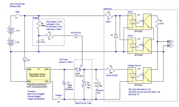
Below is a schematic for my coilgun rig. The coilgun itself is a basic single coil design that consists of an energy storage capacitor (C1), the SCR power switch (SCR1) and launch coil (L1). The charging circuit for the energy storage capacitor is a photoflash board from a disposable camera. Main power is supplied by a pair of C batteries.

(click
here
for a
larger version)
In addition to the basic coilgun circuit the schematic shows a trigger circuit and three opto-interuptors sensors. The signals from the sensors are recorded using the microphone input of a laptop computer.
Most of the parts came from my junk box. The only parts I had to buy were the Opto-interuptors, the "Silicon Power Cube" SCR and copper clad PC board.
Ref.    Description
C1     capacitor, 160uF, 330V (photoflash capacitor from the flash circuit board)
C2     capacitor, 0.1uF, 25V ceramic
D1, D3  diode, 1N4007, 1Amp, 1000PIV (what I had in the junk box, any old diode should be OK)
D2     1KV, 16A diode (part of SCR1)
L1     inductor, e.g., 40µH (air cored launch coil, hand made)
R1,R4   resistor, 47 Ohm, (all resistors are 1/4 watt)
R2      resistor, 1M Ohm
R3     resistor, 22K Ohm
R5     resistor, 4.7K Ohm
SCR1    Silicon Power Cube (1KV, 16Amp SCR and Diode, Part M25/16-1K, $4.50
 from Surplus Sales of Nebraska)
SW1,SW3 SPST miniature toggle switch
SW2 SPST NO push button switch
U1-U3 opto-interuptor, Sharp #GP1S525 (2/$1, part #OSU-55 from All Electronics)
X1     photoflash circuit from disposable camera
Other sub-miniature stereo plug
 PCB or perf board on which to construct the circuits
 bus strip(s) for the wiring connections
 insulated wire
 magnet wire (Radio Shack #278-1345)
 suitable tube for the launch coil (for example the body of a BIC pen)
 projectiles!
Disposable cameras with a flash unit contain an amazing circuit that converts 1.5 volts from a AA battery into about 320 volts. Given that these cameras typically cost about $10 these flash units must cost less than a buck to produce. I just ask the photoprocesing counter at the local grocery store (stores that actually have the photo processing machine) for used cameras. Usually they are happy to give me a couple even though they are supposed to be sent back to the manufacturer so they can be refurbished (loaded with new film) and resold. Most of the circuit boards from these cameras have a series of boxes printed in the copper trace which don't appear to have anything to do with the circuit. I believe these are where the technicians are supposed to make check marks each time the camera is refurbished. In my collection of about eight different boards one board has three marker marks in the series of boxes, suggesting it has been recycled three times. None of the other seven boards have any marks.
There are a couple different circuit boards in these disposable cameras but they are all similar and work basically the same way. Here a several links to the schematics and other useful info about these circuits; link, link, link, and one more link.
Disposable cameras contain a standard 35mm film cartridge. When new, the film is out of the cartridge and wound on a take up spool. As photos are taken the film is wound back into the cartridge. When all the photos have been taken the camera can be opened in the light since the film is safe inside the cartridge.
The images below show a typical flash circuit with various parts marked.
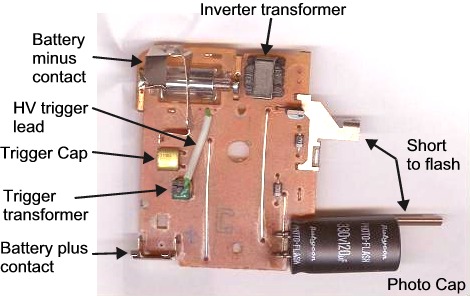
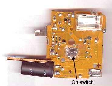
A word of caution, even though this circuit is powered by just a AA (or AAA) battery the photocap contains a significant amount of energy when charged. Use a piece of metal, held with insulated pliers, to discharge the cap before handling the circuit board. When shorted, the cap leads give a big spark and respectable bang, a "useful" characteristic on it own. Don't use anything you care about to short the cap, you'll burn holes in it. (If you look closely at the upper photo above you can see burn marks on the photo cap's leads where I've shorted it.) It is also a good idea to mark the board as you take the camera apart. Where is the battery + and -, the cap's + and -, the on switch and shutter trigger contact attached?
The images above show an unmodified circuit board. For my coilgun rig I made a few changes. The two battery contacts were removed and replaced with wires. The photo cap was removed and replaced with another pair of wires (the photo cap will be located elsewhere on the rig). The two pieces of metal labeled in the photo "Short to flash" were removed since the full 300+ volts of the photo cap is present across them. Best to get rid of them to keep from accidentally "surprising" yourself.
Lastly, the "On" switch was shorted. In the camera this pushbutton switch starts the charging cycle. When the photo cap is fully charged the circuit turns itself off. I wanted to be able to control the charging circuit with a more accessible switch, and I didn't want the circuit turning itself off. This switch consists of a domed piece of thin metal held in place with cellophane tape. This switch was shorted by removing the tape and sheet metal and shorting the contacts by soldering a piece of wire across them.
Currently, the circuit board I am using still has its "Ready" light. (The board shown above has had its "Ready" light removed, it was located in the upper right corner next to the inverter transformer.) I may remove the ready light from the board I am using since it loads the circuit somewhat, especially when the cap is above 300 volts, and may limit the maximum voltage that the circuit will charge the photocap to.
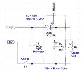 The coilgun part of the
circuit consists of the the SCR,
energy
storage capacitor and launch coil in a typical coilgun configuration.
A key component is the power switch. This switch needs to be able to handle 300+ volts and peak currents that range from a few hundred amps to several thousand amps. Not something that your typical switch can do without burning up its contacts. An SCR is a current controlled switch. Supplying a small current to the gate allows a very large current to flow between the other two contacts. SCRs do have some quirks, one of which is that the gate can not turn the SCR off. Once triggered the SCR stays on even if the gate voltage is removed. The SCR will only turn off if the gate voltage is removed and the voltage across the SCR's anode and cathode drops to near zero. The "Silicon Power Cube" SCR I used was purchased from a surplus electronics place for $4.50. It contains a 1KV 16Amp SCR and a similarly rated diode in a single package. Some quick measurements of this SCR's characteristics indicated that the anode-cathode minimum voltage for triggering is 2~3 volts and the minimum gate current is about 30mA. The pin numbers for the SCR/Diode package are shown on the schematic. (The hand written data sheet that came with power cube appears to have an error on it, the diode pins labeled 4 and 5 are reversed.)
The SCR only requires >30mA on its gate to trigger. I could have just run a wire from the battery through a push button switch to the SCR gate. That would work, more or less anyway.
There are two problems with doing it that way. First, pushing a button will give a voltage spike that is seconds long, which is typically thousands of times longer than the pulse we want the energy storage cap to supply. In addition, for certain combinations of coil and cap, the circuit will oscillate. The energy "sloshes" back and forth between the cap and coil. This "sloshing" can last several seconds. "Sloshing" is bad in a coil gun, the extended current flow time will suck the projectile back into the coil. By using a short duration trigger pulse we allow the SCR to turn itself off the first time the "sloshing" causes the voltage to drop below zero.
The second reason I used a trigger circuit is to keep the gate current from pulling down the supply voltage to the opto-isolators. I didn't want a long duration trigger pulse confusing the signals from the speed trap. (More on the opto-isolators and speed trap later.)
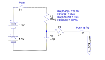 The trigger circuit is
consists of two resistors (R1 and
R2), a
capacitor (C2) and a push button switch. When the button is pushed this
circuit supplies a 3V, 60mA pulse that is about 15 microseconds long
(3RC periods) to the SCR's gate which fires the gun.
Most PCs and Laptops made in the last ten years came equipped with a sound card. The sound card is essentially an analog to digital (A/D) and digital to analog (D/A) converter. Sound cards are usually dual channel (left and right stereo channels), sample at up to 48,000 samples per second (48 kHz) with 8 or 16 bits per sample. (CD quality audio is stereo, 48 kHz, 16 bits.) The typical sound card is, therefore, a fairly powerful data acquisition system. It is possible to buy better data acquisition systems (i.e., laboratory grade A/D converters) but they are expensive. For our purposes, the sound card is more than adequate and readily available.
Sound cards may have a couple of different inputs, including "MIC", line level and system level inputs. Usually, you don't have direct access to the system level inputs, but you do have access to the MIC and/or line level inputs.
One challenge in using the laptop's sound card to record signals is figuring out exactly how the MIC input is wired inside the laptop. Apparently, there is no standard definition of what a MIC input is, this goes for both computer sound cards and regular audio components. Typically, the jack is for a 1/8" (3.5mm) stereo plug like this one from RadioShack. Even though it is called a "stereo" plug it is used in a monaural (single channel) mode here. MIC inputs are generally wired for an Electret microphone which require a power source. Power is provided either by a battery in the microphone or by the device it is plugged into. As far as I know the audio signal is always transferred on the tip of the plug and the base of the plug is always the signal ground. If the device supplies power to the microphone the power is placed on either the tip of the plug, or on the plugs ring connector. In the first case, the audio signal from the microphone and the power to the microphone are carried on the same wire.
To figure out what setup your laptop uses you need to measure the voltage between the tip and ground and the ring and ground of the stereo plug. On my Compaq Presario laptop the tip is at 2.26V (open circuit) and supplies 0.94mA (short circuit). For more information on the MIC input (and a bit on "Line Inputs") see my spud chronometer page.
I used Windows Sound Recorder (sndrec32.exe) for the recordings. I've found that to keep the signals on scale the MIC gain (recording loudness) needs to be set at the minimum value (set via the volume control panel), and the output volume also needs to be set at a low value. All of my recordings are done at 48 kHz, the maximum sample rate of my sound card. More information on the various software packages I use is on the spud chronometer page.
In order to record the muzzle velocity and the voltage profile of the capacitor-coil combination we need a way to produce a signal suitable for recording by the laptop's sound card. However, it would be a bad thing if the 300+ volts from the coilgun found its way into the laptop's MIC input.
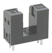 A convenient
way to isolate the high voltage of the coilgun from the low voltage
required by the MIC input is to use an optocoupler. If we
use opto-interuptors then we have both electrical isolation and a
convenient light path that can be blocked by a projectile for use as a
speed
trap. I used a pair of modified Sharp GP1S525 opto-interuptors (2 for
$1.00 from All Electronics) for my speed trap. At the right is an
enlarged
image of this opto. The two arms are separated by an 0.2" (5mm) gap.
The arm with an "S" on top contains a phototransistor. The arm with the
"E" on top contains an infrared LED. You can see the window for the
phototransistor at the top of the "S" arm. When power is supplied to
the LED the light shines across the gap and illuminates the base of the
phototransistor causing it to conduct current. The data sheet for the
GP1S52 series of optos says the transfer efficiency is about 5%, so
a 20mA current through the LED allows 1mA to flow through the
transistor.
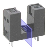 The gap
between the two arms is only slightly larger than the
diameter of a BB (0.2" versus 0.177"), so I modified the opto by
slicing
the two arms apart as shown by the blue plane at right.
Since
there are no electrical paths between the two arms slicing them apart
does not affect the functioning of the opto-interuptor. The mounting
holes on a PCB were
laid out so that the gap between the two arms was increased by 0.1" to
a total of 0.3".
For a "voltage detector" I used an unmodified opto-interuptor, though I covered it with a piece of aluminum foil to keep room light from the detector. (Careful that the foil doesn't short the opto's electrical contacts, 300+ volts into the MIC is a bad thing!)
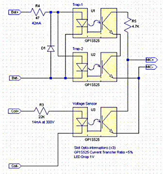 The circuit for the speed
trap and voltage monitor is
shown to the right.
For the speed trap, R4 limits the current to the trap LEDs to 42mA
total. The two LEDs are wired in parallel so it they will work
with a 1.5V power supply. The output side of the trap optos are wired
in series with each other and a 4.7K resistor (R5) and connected
to the MIC+ and MIC- leads. Since the traps are in series, blocking
either one results in less current draw by the
circuit and a rising signal to the sound card. Diode D1 is probably not
needed but was inlcuded to insure that the LEDs never see a
reverse bias.
The voltage sensor opto is wired in series with a 22K current limiting resistor (R3), across the launch coil. With an input of 300V R3 limits the current through the LED to 14mA and nearly all the voltage is dropped across the resistor. The output side of this opto is connected directly to the MIC plus and minus. When the gun is fired the voltage across the launch coil turns on the LED which in turn turns on the phototransistor which sinks current from the MIC input. The net result is a negative going spike in the recording for a positive going voltage across the coil. The voltage detector opto LED is protected by the main diode, D2 (included in the "Silicon Power Cube"), so it should never see a reverse bias.
Of course, for both the input and output sides of all three optos, it is important to get the polarities correct.
The circuitry on my rig is pretty simple. It could easily be constructed using "point to point" wiring between several bus strips, or on a small piece of perf board. The only critical alignment is of the speed traps with the line of flight of the projectile. Since I needed to get the speed traps aligned and held firmly in place, I decided to go ahead and make a printed circuit board (PCB) to hold most of the small electronic components. It had been nearly 30 years since I made a PCB so I'm a bit rusty at it.
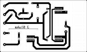
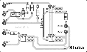
I used ExpressPCB software to lay out the components and traces. I couldn't find a suitable mask for the opto-isolators so I modified the standard DIP pattern by adding several additional holes for each pin on one side of the opto. The copper trace side and component ("silk screen") side images are shown below. The "1 inch" line near the center of the component side gives the correct scaling for the board.
| Copper
Trace
Side (image reversed): |
Component Side: |
 |
 |
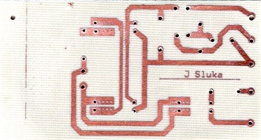
The pattern for the copper trace side was laser printed on a piece of glossy laser printer photo paper. The pattern was then transferred to a cleaned piece of single sided copper clad board with an iron (google "laser printer PCB" for pages with detailed directions). The board was etched in a mixture of 1 part Muriatic Acid (aka Hydrochloric Acid, available at garden centers, hardware and drug stores) and 3 parts 3% hydrogen peroxide (drug store). I warmed the solution slightly in a microwave before putting the board in. It took about 10 minutes to etch the board, after which the laser printer "ink" was removed with mineral spirits. Below is a scan of the etched and drilled board. Not the prettiest, but more than adequate.
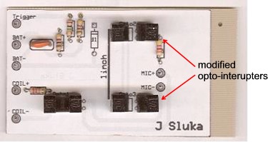
To the right is a scan of the top of the populated board. The component side pattern was printed on a blank label and stuck to the top of the board before the components were installed. Diode D1 hadn't been installed (but has since been) and the various off-board wires had not yet been connected.
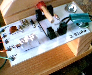 The
completed circuit board was mounted on a
small block of wood with screws. I oversized the holes in the PCB
so it can be moved a
bit to fine tune the alignment of the two trap optos with the
projectile's flight path. A really bad photo of the installed PCB is
shown to the
right. Note the piece of aluminum foil covering the voltage detector
opto. An alignment stick is shown extending from the muzzle showing
the alignment of the projectile path with the speed traps. (This photo
was taken with a 0.1 Mpixel camera I got for free, hence their
incredibly poor quality.)
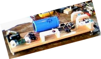 The various parts were mounted on a piece of wood similar to Barry's
setup. The front edge of the board has two feet which tilt the board
and
barrel up at a 5° angle to keep the BB's from rolling out of the
barrel. The PCB board was mounted below the muzzle of the gun. The
"Power", "Charge" and "Fire" buttons were mounted on a small piece of
acrylic near the center of the board. Many of the electrical
connections were made using two bus strips screwed to the
board.
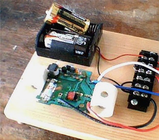 The mounts for the photoflash board were made from 1" long pieces of
3/4" CPVC pipe. The pipe pieces we sliced down one side and the
photoflash board slipped into the slice. A hole was drilled through
both sides of the pipe then enlarged on one side so a screw driver
could reach through the pipe to a wood screw on the other side. The
left hand mount is nearly impossible to see in the bad photo.
The coil end of the rig is shown below in another bad photo.
The top
of the barrel mounts are removable (two of the four screws are barely
visible in the photo) so the barrel/coil can be easily replaced.
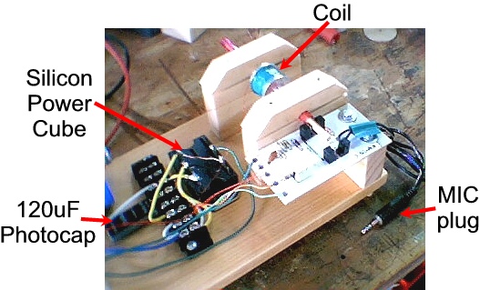
The control panel portion of the jig is shown below in yet
another
bad
photo.
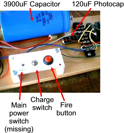
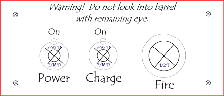
Below is the label I used for the
control panel.
Using this rig is straight forward. The MIC plug is plugged into the laptop's MIC input. Sound Recorder is started and set to record at 48 KHz, 8-bit, mono. A BB is loaded and positioned with an "alignment stick". The "Main" and "Charge" switches are turned on. (I monitor the voltage across the capacitor with a DVM.) When the cap is fully charged I turn the "Charge" switch off, start the recorder and press the "Fire" button. The recording is stopped and saved to a file.
The "alignment stick" (below) is a 3/16" wood dowel marked with 2mm gradations. The gradations allow for reasonably precise positioning of the BB in the barrel. The stick, and the 5° tilt of the jig, holds the BB in place. The central gradation on the stick places the BB's center at about the beginning of the coil.

I've found that the speed trap optos transmit the charging "whine" of the flash board to the sound card, which is why I turn the charge circuit off before firing.
| So, does it work? |
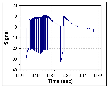 Pointing
an
infrared TV remote control into the "Voltage Detector"
opto-interuptor gives the signal shown at right. This is
strictly a "go - no go"
type test of the TV remote control and simply verifies that the remote
is
blinking its infrared LED. Here
is what it
sounds like. If the remote is pointed into one of the speed trap
opto-interuptors a similar signal is obtained though the amplitude is
less because of the current limiting resistor (R5) in the MIC side
of the trap circuit.
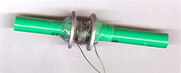 The
first test coil is shown at the right. The coil was made using 26G wire
wound on the body of a pen. A pair of 3/4"D by 1/16" steel washers
were used to constrain the coil and aid in winding. The washers and top
layer of the coil are held in place with hot-melt glue. The various
parameters of the coil are listed in the table below. (Note that this
coil is not the same as shown in the photos of the rig.)
| Coil Parameters | ||
| Wire | 26 | Gauge |
| Coil Length | 0.31 | inch |
| Coil Width | 0.44 | inch |
| Coil ID | 0.3 | inch |
| Barrel ID | 0.21 | inch |
| Number of Turns | 70 | |
| Number of Layers | 4 | |
| Measured Resistance (approximate) | 0.2 | Ohm |
| Estimated Inductance | 30 | uHenries |
| Capacitor Parameters | ||
| Capacitance | 160 | uFarad |
| Voltage Rating | 330 | Volt |
| Energy (at 320V) | 8.2 | J |
| Coil + Capacitor Parameters |
||
| Calculated 1/2 Wave Time | 0.226 | mS |
| Calculated Peak Current | 504 | A |
| Ipeak x Turns | 35,300 | AmpTurns |
| Projectile Parameters | ||
| BB Diameter | 0.177 | inch |
| BB Mass | 0.34 | gram |
An RLC analysis of this coil is shown below. This analysis was generated using Barry's truly excellent RLC simulator. This coil+cap combination is expected to oscillate ("slosh") somewhat and to give a peak current of ~500 amps with a half-wave time of 0.226mS. Of course, this simulation is based on my estimate of the inductance and resistance of the coil which does not take into account the steel washers or the affect of the BB. In addition, since my coil gun setup has a reverse biased high voltage diode (D2) wired across the coil, the voltage can never go more negative than about one volt and oscillation ("sloshing") is completely removed.
The results for this coil and capacitor combination are shown in the graph below. The wav file is here if you would like to hear what it sounds like.
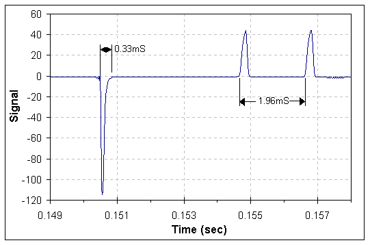
The negative spike represents the voltage versus time across the coil as measured by the "Voltage Detector" opto-interuptor (U3). The two positive peaks are from the BB passing though the pair of opto-interuptors (U1 and U2) that make up the speed trap.
The measured time between the two trap peaks is 1.96mS. Since the traps are one inch apart the muzzle velocity can be calculated from;
muzzle velocity = (1")(1'/12") / (0.00196s) = 42.5 fps
This recording was made using the sound card's maximum sampling rate of 48 kHz. At this sampling rate data points are every 0.0208mS, which is about 1% of the total time between the two trap peaks.
The width of the voltage peak, at its base, is about 0.33mSec. Barry's RLC simulation indicated that this coil+cap pair should have a voltage width (1/4 wave) of about 0.11mSec. There a several possible explanations for this difference. The most obvious is simply that my estimation of the inductance and resistance of the coil are not very accurate. There are several other possibilities as well. The SCR, infrared LED and sound card all have finite response times which may be stretching the width of the peak. Or, the output of the voltage detector may not be an accurate representation of the actual voltage versus time profile.
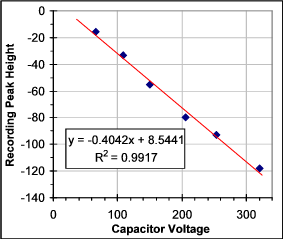 To see if the "Voltage Detector" opto-interrupter gives a signal
that is linear with the input voltage, I examined the affect of changing
the charge voltage on the capacitor. This was easily done by monitoring
the cap's voltage with a voltmeter and turning off the "Charge" switch
when the desired voltage was reached. The gun was then fired and the
voltage detector output recorded. The graph at the right shows the
peak height from the sound recording plotted against the capacitor
voltage. It appears that the response does indeed mirror the voltage.
If
we extrapolate the data to the point where the recording peak height
would be zero we find that the capacitor voltage would be 21.1V and the
voltage detector LED current, which is limited by R3, would be 1mA. So
it looks like this setup will work with voltages down to about 20V. For
lower voltage ranges a smaller value for R3 could be used to extend the
low end of the useable voltage recording range. However, care must be
taken not to exceed the current rating of the voltage detector's LED.
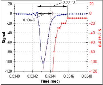 I would like to be able to use the width of the voltage peak as a
measure of the 1/4 wave time of the coil+cap combination
since this is
a critical characteristic of a coil gun. It appears that
the voltage detector is giving a reasonable representation of the
voltage. But what about the time? The width of the voltage peak should
be the 1/4
wave time of the coil+cap combination. But what would be the best way
to measure the peak width from this data? The peak tails making it
difficult to
decide where it hits zero volts. The graph at right shows a
typical curve from the voltage detector. I've added a 10X
overlay, in red, to the graph to make the "zero reading" (actually -1
in this case) more evident. Using this "zero reading" method to define
the end of the peak gives a 1/4 wave peak width of 0.33mS which is
probably an overestimation.
Another way of measuring the peak width, which is useful for peaks that tail badly, is to draw a line though the linear portion of the falling edge and extrapolate to where the peak would have reached zero if it didn't tail. The purple dashed line on the graph shows this estimation, from which a 1/4 wave time of 0.18mS (0.36mS 1/2 wave) is obtained. This is considerably closer to the RLC simulation's estimate of ~0.11mS and is probably the best way to measure the wave time with this setup.
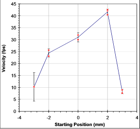 Coilguns are sensitive to
the starting position of the
projectile. The graph at right shows a plot of the muzzle velocity
versus the starting position of the BB. The
"0 mm" position places the center of the BB at approximately the edge of
the the coil. As you can see in the graph, the BB's starting position
must be within about a 6mm (1/4 inch) window for it to fire.
Furthermore, changes of only one
millimeter (1/25 inch) in either direction significantly affect the
muzzle velocity.
One common way of measuring the efficiency of a coilgun is to compare the electrical energy in the capacitor with the energy of the launched projectile. In a 100% efficient gun all the energy in the capacitor would end up as kinetic energy of the projectile.
| Kinetic
energy of a projectile: |
Ekinetic = 1/2(mass)(velocity)2 | |||||||||
| Energy
in a capacitor: |
Ecap = 1/2(capacitance)(voltage)2 | |||||||||
| Efficiency: |
|
|||||||||
| mass=0.00034kg, velocity=13 m/s(42.5fps) capacitance=160uF voltage=320V |
(0.00034)(13)2 (0.00016)(320)2 = 0.35% |
Coilguns are notoriously inefficient ways of launching projectiles but still, 0.35% is not very impressive.
Another way to measure the efficiency is to compare the observed velocity with the expected velocity calculated from the projectile's starting distance to the center of the coil and the time length of the current pulse. In this case, a "100% efficient" gun actually gets its projectile up to the expected velocity. In other words, the distance divided by the cap discharge time is equal to the muzzle velocity. This coil is 0.31" long and the BB's optimal start position is about at the edge of the coil. For an optimal launch the BB should move 0.155" in the time the current pulse lasts. This cap+coil combination appears to have a 1/4 wave time of 0.18mS so the 1/2 wave time is 0.36ms. Dividing the distance by the time and converting to feet per seconds gives an expected average velocity of (0.155")(1'/12")/0.36mS = 36fps. For acceleration in a uniform force field the final velocity is twice the average velocity so the predicted, "100% efficient", velocity is 72fps.
Vmax =2d / (1/2 wave time)
(Actually, since the field is uniform in neither space nor time, this is not a very accurate approximation, but it is still useful.) Comparing the squares of the velocities (the energy is proportional to the square of the velocity) the observed velocity of 42.5 fps is 35% efficient by this measure. (Which sounds a whole lot better then 0.35% efficient!)
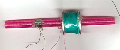
This coil was wound on a BIC pen body using 30G
magnet wire. A
small coil of 26G wire was included on the barrel to test if I could
use an inductive position sensor with the PC sound cards MIC input.
This was actually the first coil I wound and its inductance is too high
(it has too many turns) for the capacitor and projectiles being used.
With a predicted 1/2 wave time of 4.4mS and a half coil length of 0.31
inch the estimated "100% velocity" is only about 11.7fps.
| Coil Parameters | ||
| Wire | 30 | Gauge |
| Coil Length | 0.63 | inch |
| Coil Width | 0.83 | inch |
| Coil ID | 0.31 | inch |
| Barrel ID | 0.20 | inch |
| Number of Turns |
1430 |
|
| Number of Layers |
23 |
|
| Measured Resistance (approximate) | 20 | Ohm |
| Estimated Inductance | 12,000 | uHenries |
| Capacitor Parameters | ||
| Capacitance | 160 | uFarad |
| Voltage Rating | 330 | Volt |
| Energy (at 320V) | 8.2 | J |
| Coil + Capacitor Parameters |
||
| Calculated 1/2 Wave Time | 4.4 | mS |
| Calculated Peak Current | 12 | A |
| Ipeak x Turns | 17,160 | AmpTurns |
| Projectile Parameters | ||
| BB Diameter | 0.177 | inch |
| BB Mass | 0.34 | gram |
For an LC circuit:
For a Coil:
For a Coilgun:
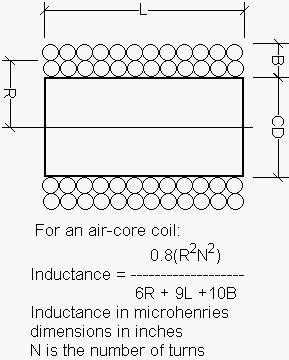
The formula below is used to estimate the inductance of a solenoid (air cored electromagnetic coil). For best results the coil's length (L) should be large compared to the core diameter (CD).
Coil gun links
Disposable Camera Flash Hacking Links
Send me an email
Modified:
3 January
2020
©2006--2020 James Sluka