The test chamber was constructed from a 46" long by 1.69" diameter (aspect ratio 27:1) polycarbonate fluorescent lamp protector tube. These clear polycarbonate tubes are available at most hardware stores for a couple bucks each. The setup is shown below.
I closed the ends of the polycarbonate tube with plastic wrap
held in place with rubber bands (see photo below of the spark gap end
of the chamber). The chamber could be described as a "semi-open" tube;
at low pressures the chamber is well sealed, a modest rise in pressure
will blow the plastic wrap end caps off the chamber and limit the peak
pressure in the chamber.

The spark gap consists of a pair of "un-popped" pop rivets hot glued into holes in the tube. The ignition source was a "100KV" stun gun.
To make the small (0.05"D) filling vent hole visible I highlighted
it with a black marker (visible in the photo above).
68cc of propane (4% of the chamber volume) was measured with a
syringe and injected slowly into the small hole on the end of the tube
opposite from the spark gap. The small vent hole on the spark end was
also open during injection. The holes were covered
with blue painter's tape after fueling. The blue tape survived repeated
firings
of the tube, without perforating or being dislodged, even though it was
peeled back and then reapplied for each refueling.
I have
recorded videos of the chamber firing. Unfortunately, I don't have
access to a high speed video camera so I had to make do with the video
mode of a 6MP digital still camera.
During fueling I tried to get the fuel to
mix as much as possible by injecting the fuel at a high rate with the
syringe needle pointed towards the far end of the tube. The tube was
inverted slowly several times and then left to sit for about one hour
before ignition.
A QuickTime video is here (465KB).
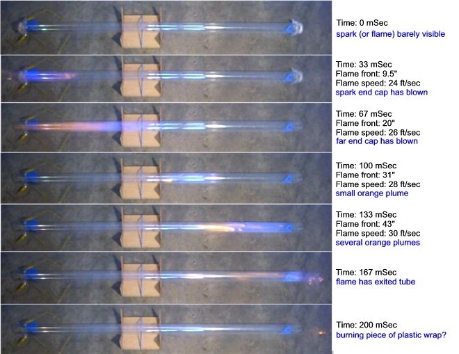
Below are the six frames of video that span the entire combustion
event. Note that the distances are very rough approximations.
The times are calculated based on a 30 frames per second video rate.
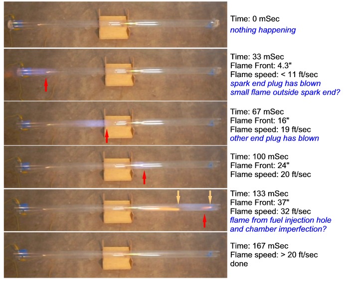
In the first frame nothing has happened yet, this is the zero time point.
In the next frame ignition has occurred and the spark-end plastic
wrap plug has been blown off.
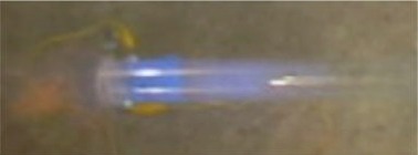
There is a faint orange smudge to the
left of the tube's end which may be the plastic wrap blowing off or,
given the orange color, a flame. The denser blue color is the tape that
covered the vent hole, the fainter blue smudge is the flame. The flame
appears rather diffuse. This is probably caused by the relatively slow
shutter speed of the camera. It may also be caused by a turbulent,
instead of laminar, flame front.
The next three frames show the flame propagating the length of the
tube, in the final frame combustion has finished. The blue color of the
flame suggests that the fuel was indeed well mixed.
The fifth frame has some very interesting features:
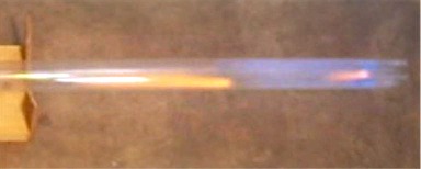
The white streaks are simply room light reflecting off the outside of
the tube. The broad blue smudge is the flame "front". The somewhat
sharper and
bluer smudge near the end of the tube is the blue tape that covered the
injection hole. The interesting features of this frame are the two
orange and pink "plumes". The smaller plume near the end of the pipe
appears to be coming from the injection hole (the tape
on the outside of the pipe was not dislodged during firing). The larger
plume near the center of the flame is caused by ...? Close inspection
of the tube reveals a small scratch on the inside of the tube which
appears to be the source of the plume. So it appears that any flaw in
the tube, even something as minor as a covered 0.05"D hole or small
scratch causes an orange plume. An orange flame color for a propane in
air combustion suggests incomplete combustion caused by insufficient
oxygen (an "oxidizing flame"). I wonder if the rough edges and/or
turbulence around the surface flaws is causing the polycarbonate to
burn. The color is due to an excess of fuel. Inspection of the flaw and
hole show no visible signs of
combustion. If the polycarbonate is burning then very little plastic is
actually being consumed in the process.
There is another interesting characteristic of these two plumes.
Which direction do the plumes suggest the gases in the tube are moving
at this particular instant in the firing cycle? The plumes suggest that, though
the flame front is propagating to the right, the gases in the tube are
moving to the left. The length of the larger plume suggests that
the gas speed is similar to the flame speed (~30ft/sec) but in the
opposite direction. Apparently, the combustion gases to the left of the
plume have cooled significantly, dropping the pressure below
atmospheric,
resulting in a large "suck-back" of air into the tube. This is
reminiscent of the flame and gas movement in a pulse-jet engine.
I wonder if I reached into the chamber with a nail on a stick and
made small scratches every foot or so along the length of the tube if
that would allow me to determine the direction and speed of the gas's
movement at different places in the chamber as it is fired? Each small
scratch would be the source of a plume, the plume direction and length
would indicate the gas speed and direction at a particular instant.
For this video I attempted to get the chamber to fire without fully
equilibrating the fuel. The fuel was injected slowly and allowed to
diffuse for ~30 minutes, roughly two diffusional half-lives for this
chamber. You can view the QuickTime video here
(1.3MB).
The second and third frames have orangish flames that do not appear
to be associated with imperfections in the tube. Presumably this
coloration is due to incomplete mixing of the fuel.
As in the first video, some of the frames have plumes that appear to
be associated with flaws in the tube. The fourth frame has a single
small plume, the fifth has a couple plumes.
For the next video I injected sufficient fuel to bring the chamber
to about 7% propane. The mixture is very rich and near the upper
combustion limit or propane in air. You can view this video here
(3.4MB).
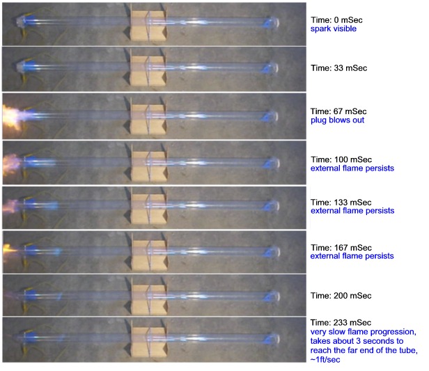
Note that in the image above only the first frames are shown, there
are an additional ~90 frames showing the flame front
progressing through the tube.
The rich mixture gave a robust blow-out
flame at the spark end which lasts ~130mSec. The flame front then
proceeded down the tube very
slowly, taking about 3 seconds to reach the far end. At the far end it
burned through the plastic wrap plug. This very rich mixture gave a
flame speed in the tube, after the initial blowout, of only about 1
foot/second, more than an order of magnitude slower than the shots with
stoichiometric fuel. The slow burn speed may be a result of the need to
suck fresh air into the tube, from the chambers spark end, to support
combustion. Since the injection end cap was never blown off, air can
only enter the tube via the spark gap end.